Featured Product
New LAUDA Integral XT 280
Highly Dynamic Thermostat for External Process Control and Reactor Chemistries from
-80 °C to 200 °C.
Select up to 3 products to compare: Compare Products
LAUDA through-flow coolers and immersion coolers are used as add-on devices to cool heating thermostats or any type of bath below ambient temperature. The preferred use of through-flow coolers is the use in conjunction with heating thermostats and integration into the cooling circuit.
LAUDA immersion coolers provide a quick way to extend the temperature range downwards when used in conjunction with heating thermostats, water baths and cooling traps. The thermostats work on the classical principle of direct evaporation, and the flexible hose connection means that they can be used without any problems. The ETK 50 even has adjustable temperature control.
| Technical features | ETK 30 | ETK 50 | ||
| Select to compare: | ||||
| Working temperature range (without external heating) | °C | -40...20 | -50...20 | |
| Operating temperature range (with external heating) | °C | -40...100 | -50...100 | |
| Temperature probe | – | Pt 100 | ||
| Control action | – | 2-point action | ||
| Temperature stability (at -10 °C) | ±K | – | 0.5 | |
| Cooling output at | 20 °C | kW | 0.15 | 0.25 |
| -10 °C | kW | 0.13 | 0.25 | |
| -30 °C | kW | 0.04 | 0.20 | |
| -40 °C | kW | 0.01 | 0.10 | |
| -50 °C | kW | – | 0.04 | |
| Cooling unit | air-cooled fully hermetic | air-cooled fully hermetic | ||
| Cooling coil (Ø x L) | mm | 42x124 | 52x166 | |
| Base area (W x D x H) | mm | 250x360x285 | 460x410x270 | |
| Weight | kg | 17 | 33 | |
| Power consumption | kW | 0.2 | 0.3 | |
| Cat. No. 230 V; 50/60 Hz | LFE 002 | on request | ||
Select up to 3 products to compare: Compare Products
LAUDA through-flow coolers upgrade any type of heating thermostat with pump connections to a high-quality cooling thermostat and thus allow working below ambient temperature. 
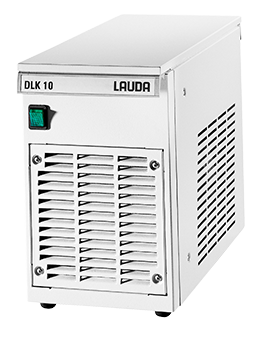
Through-flow coolers replace cooling with tap water that is expensive and ecologically not recommandable. They provide a constant flow and temperature of cooling supply regardless of the variations. Therefore, it is possible to ensure optimum temperature stability over the entire period and allow reproducible temperature conditions at any time.
| Technical features | DLK 10 | DLK 25 | DLK 45 | DLK 45 LiBus | ||
| Select to compare: | ||||||
| Working temperature range | °C | -15...150 | -30...150 | -40...150 | -40…150 | |
| Cooling output at | 20 °C | kW | 0.25 | 0.33 | 1.1 | 1.1 |
| 0 °C | kW | 0.20 | 0.28 | 0.95 | 0.95 | |
| -10 °C | kW | 0.10 | 0.25 | 0.85 | 0.85 | |
| -20 °C | kW | – | 0.22 | 0.75 | 0.75 | |
| -30 °C | kW | – | 0.20 | 0.55 | 0.55 | |
| -40 °C | kW | – | – | 0.30 | 0.30 | |
|
Heat exchanger connections for heat carrier |
M 16x1, nipples Ø 13 mm |
||
| Special features | Control connection for mains supply |
Proportional cooling: Ultras |
Proportional cooling: Proline |
|||
| Overall dimensions (W x D x H) | mm | 200x400x320 | 290x540x330 | 470x560x430 | 470x560x430 | |
| Weight | kg | 17 | 33 | 63 | 63 | |
| Power consumption | kW | 0.2 | 0.5 | 0.9 | 0.9 | |
| Cat. No. 115 V; 60 Hz | LFD 710 | LFD 708 | – | – | ||
| Cat. No. 208-220 V; 60 Hz | – | – | LFD 809 | LFD 811 | ||
Select up to 3 products to compare: Compare Products
LAUDA UWT circulation heat exchangers are an economical alternative to circulation chillers when central facility cooling circuits can be used. This is economically and ecologically practical if heat removal from processes has to be performed either regularly or at a high power, and the removed heat should not enter the ambient environment. Regulated circulation heat exchangers – also known as system separators – guarantee temperatures, pressures and volume flow rates adapt to the application. The LAUDA UWT take cooling water from an existing primary circulation system and thermostat an internal bath volume in an individually-adjustable manner: this bath volume is then transported to the application via a pump in the laboratory circulation system.
Schematic circuit diagram of LAUDA circulation heat exchangers
A: Application
B: UWT
C: Facility cooling supply
a: Inlet of coolant
b: Return flow of coolant
c: Flow pipe for application
d: Return pipe for application
1: Heat exchanger
2: Bath vessel with heat tranfer liquid
3: Immersion pump for circulation
4: Pressure indication for UWT 6000 and UWT 10000
| Technical features | UWT 3000 | UWT 6000 | UWT 10000 | |
| Select to compare: | ||||
| Working temperature range | °C | 8…25 | 8…25 | 8…25 |
| Resolution of setting | °C | 0.1 | 0.1 | 0.1 |
| Resolution of indication | °C | 0.1 | 0.1 | 0.1 |
| Temperature stability | ±K | 1 | 1 | 1 |
| Cooling capacity | kW | 3 | 6 | 10 |
| at coolant inlet temperature | °C | 9 | 9 | 9 |
| at coolant pressure loss | bar | 0.12 | 0.05 | 0.07 |
| at cooling circuit volume flow | L/min | 6 | 16 | 20 |
| at laboratory circuit inlet temperature | °C | 14 | 14 | 14 |
| at output UWT | L/min | 6 | 6 | 20 |
| Pump pressure max. | bar | 1.0 | 1.0 | 2.2* |
| Flow max. | L/min | 30 | 30 | 33 |
| Cooling and lab circuit connections | G 3/4 | G 1 1/4 | G 1 1/4 | |
| Filling volume | L | 7...12 | 35...45 | 35...45 |
| Overall dimensions (W x D x H) | mm | 350x480x410 | 550x650x480 | 550x650x480 |
| Weight | kg | 34 | 68 | 74 |
| Power consumption | kW | 0.2 | 0.2 | 0.5 |
| Cat. No | on request | on request | on request | |
*Also available with more powerful pump with 5.5 bar (LSW 1202); 40 L/min